Generating g-code file in CAM
 |
| -Click to Go Back |
Creating a New CAM Setup
Switch to the Manufacturing workspace to start programming CAM.
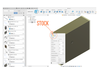
Begin by clicking the Setup menu in the toolbar and select New Setup. A small panel will open three tabs: Model, Stock, and Post Process. The Model tab sets the work coordinate system (WCS) for the model. The Stock tab sets up the dimensions of the piece of material (or “stock”) you’ll be milling.

Stock size: Click the Stock tab and select the “Fixed size box” mode. Then you can adjust the dimensions of the stock. Measure your stock using digital calipers and enter the dimensions of your stock by entering exact values into the Width (X), Depth (Y), and Height (Z) boxes. The smaller the stock size, the more efficient your toolpaths will be.
Model orientation: Fusion 360 places your model in the exact center of your stock. You may want to align your model to the surface of your stock or offset it to gain some efficiency. It is better to orient the model within the stock to optimize your milling. In the Stock tab, click Model Position under Height, select Offset from Bottom, and enter 0”. This will make the bottom of your stock and model the same.
Work Coordinate System WCS: Specify the coordinate system that the toolpaths will use to mill. To set up a work coordinate system (WCS), you’ll configure the directions of the X, Y, and Z axes to match those on your desktop CNC machine. You will also choose the point that will serve as the origin (coordinate 0, 0, 0).
It is good to have a preview of the model and the coordinates. You can specify both the position of the stock on the machine and the position of your file relative to the stock.
The machine origin position is the front left corner of the base plate.
The material position is relative to this machine base origin.
To specify your WCS go to the Setup tab, select Stock box point for your Origin point, and then select the top, front, left box point on your stock. Then click OK.
Advanced Work Coordinate System Setup
Fusion 360 allows you to orientate your tool in a few different ways.
Model Orientation: This aligns your tool with the axis of the WCS associated with your model.
Select Z Axis/Plane & X Axis: Allows you to choose the Z & X axes yourself, using your model's geometry.
Select Z Axis/Plane & Y Axis: Allows you to choose the Z & Y axes yourself, using your model's geometry.
Select X & Y Axis: Allows you to choose the X & Y axes yourself, using the model geometry.
Select Coordinate System: This allows you to align your tool with a User Coordinate System in the model. This option is helpful if your part doesn't have points or planes that are easy to select.
Note: No matter which of these you choose, make sure that your Z-axis is always pointing away from the stock.
When working with APSX Spyder CNC Machine, we recommend using the “Select Z axis/plane & X axis” option. To select this option, go to the Setup Tab and under the Work Coordinate System (WCS) > Orientation > "Z axis/plane & X axis." The options available will look like this:

Click the button next to “Z Axis” and then select a face or line on your model that would be lying flat in your CNC Machine.
You should see the blue Z-axis indicator stick out from the face you selected and pointing in the positive direction.
Next set the X-axis orientation following the same procedure you followed for the Z-axis. If it’s already oriented correctly, you don’t need to do anything.
Finally, select "Stock box point" for the Origin. Beneath the dropdown menu, click Box Point and then select the point in the front, top, left corner of the stock.
Toolpaths
Now you need to program your toolpaths. Keep in mind that some parts may require multiple toolpaths, multiple tools, and even multiple setups. There are many toolpaths to choose from and they all have different strengths and weaknesses. Fusion 360 has helpful information panels that pop up when you mouse over the different toolpaths. To learn more about them, hover your mouse over the toolpath you wish to program.
Programming Toolpaths
When you select a toolpath, a new panel will pop up. This panel has five tabs, each with a number of settings and places to enter your speeds and feeds recipes.
Tool is for selecting a tool and specifying your speeds and feeds.
Geometry is for selecting the geometry you wish to mill.
Heights is for specifying vertical dimensions of the toolpath.
Passes is for configuring the depth of passes, stepover, and stepdown.
Linking is for specifying how the toolpath will begin and end. This tab becomes especially helpful when programming multi-operation setups.
Speeds and feeds recipes are essential for CNC machining operations because they’re what we use to define our cutting parameters for the toolpaths we program.
For a three-axis CNC Machine, there are five key cutting parameters to define when programming CAM:
Spindle speed (RPM, revolutions per minute) relates to how quickly the cutting edge moves along the material.
Feed rate (IPM, inches per minute) controls how quickly the tool moves through the material.
Plunge depth is the speed at which the end mill is driven down into the material when starting a cut.
Stepover (RDOC, radial depth of cut) is how much space there is between tooling passes when cutting a material.
Stepdown (ADOC, axial depth of cut) is how deep your tool cuts into the material.
Tool Tab
In the Tool tab, click the Select button and choose your end mill. For toolpaths where you need to clear a lot of material, we recommend using 1/4” flat end mill.
Geometry Tab
Create a machining boundary by selecting the Silhouette and then enter a value for the boundary. When deciding on how large or small the boundary should be, take into account the size of your tooling and your fixturing so you don’t break an end mill or have a collision.
Heights Tab
Clearance Height: This height should always be set above all features on the model so that you avoid plunging your tool into any part features when doing linking moves or moving at a rapid feedrate.
Retract Height: This height tells the CNC Machine how far to retract after performing an operation.
Top Height: This allows you to set an upper boundary for certain operations and will usually be just the top of your model.
Bottom Height: This setting specifies the lowest height you want the operation to machine.
Passes Tab
For adaptive toolpaths, the Optimal Load is essentially the stepover, and Maximum Roughing Stepdown is the stepdown.
Note: To learn more about the Heights and Linking tabs, we recommend checking out this NYC CNC walkthrough: https://www.nyccnc.com/walk-tabs-fusion-360-cam-operation/
Simulate Your Toolpath
Select a toolpath and click the Simulate icon under Actions in the toolbar.
Make sure Stock is checked so that you can see the toolpath being machined. Click the Play button at the bottom of your screen. If the tool turns red, there will be a tool collision. Head back into the toolpath and make adjustments as needed.
Post Process: Generating G-code Files
When you’re finished programming your CAM and simulating your toolpaths, the next step will be post-process your G-code files. Post processing is the component of your CAM software that translates the CAM toolpaths you’ve programmed into the exact G-code dialect that APSX Spyder CNC Machine can read. You can post-process your toolpaths by right-clicking on the toolpath you wish to post-process and selecting Post Process in the menu.
When you select Post Process, a new window that looks like this will pop up:
In the Post Process window that pops up, select Personal Posts for your Source. Click the Post Processor dropdown menu and select “APSX Spyder” enter the rest of the information as needed.
You’ll also notice there are other pieces of information you can fill out.
Program Number is a number that will show up in the file so you can tell which order the file is supposed to be cut.
Program Comment allows you to enter a description.
For Units, be sure that “Document Unit” is selected.
Leave “Minimize tool changes” unchecked.
Uncheck “Open NC file in editor” unless you want to make manual changes to the G-code.
Leave all the Properties values as-is.
Click OK.