Injection Molding Concept
 |
| -Click to Go Back |
Injection Molding Concept
*
What is Injection Molding?
Almost every plastic part around you was manufactured using injection molding: from car parts, to electronic enclosures, and to kitchen appliances.
Injection molding is a manufacturing process for the mass-production of identical plastic parts with good tolerances and mechanical properties. Plastic pellets are first melted and then injected under pressure into a mold, where the liquid plastic cools and solidifies. The materials used in Injection Molding are thermoplastic polymers that can be colored or filled with other additives.
How do Injection Molding Machines Work?
All thermoplastic materials can be injection molded. Some types of silicone and other thermoset resins are also compatible with the injection molding process. The most commonly used materials in injection molding are:
- Polypropylene (PP): ~38% of global production
- ABS: ~27% of global production
- Polyethylene (PE): ~15% of global production
- Polystyrene (PS): ~8% of global production
There are mainly three parts in the injection molding machine:
Injection
The injection section of the machine melts the plastic pellets and pushes them into the mold. The components of this section are the hopper, the barrel and the plunger or screw.
You place the plastic pellets into the hopper. They are pushed into the barrel where they are heated. The plunger moves the molten plastic into the mold by applying the injection pressure. The plastic solidifies inside the mold and takes the shape of the mold cavity. As the final step, the mold opens and the part is ready.
This cycle repeats and may take about 60 seconds with APSX-PIM.
Mold
It makes up a big portion of the start-up costs in injection molding. The cost of a typical mold starts at approximately $1,500-3,000 for a simple geometry and can go upwards to $6,000-10,000 for molds optimized for complex parts.
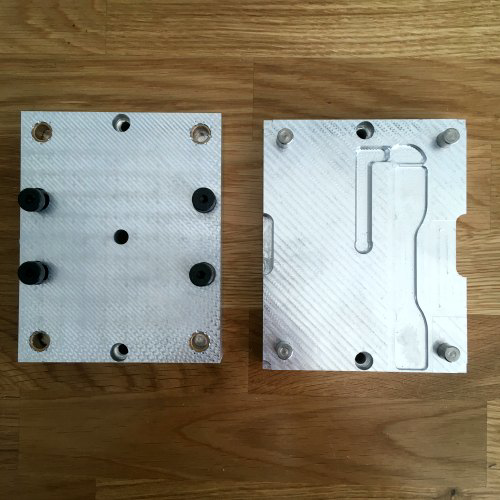
Molds are usually CNC machined out of aluminum or tool steel. Recent advances in 3D printing materials have enabled the manufacturing of molds suitable for low-run injection molding (100 parts or less) at a fraction of the cost. However, machining aluminum molds are not too expensive and time consuming compared to 3D printing.
Straight pull molds have two halves: Cavity and core. They require 2D geometry simple parts. For more complex parts, you may need to add side action inserts to the mold. It adds complexity and cost to the process.
The mold has the sprue, the runner and the gate features. There may be one or more runners in a mold. The gate is the entry point of the material into the cavity. Its size and shape is critical and should be designed for a specific material.
Clamping
Other side of the injection molding machine is the clamping system. The clamping system has a dual purpose: it keeps the 2 parts of the mold shut during injection and it ejects the part out of the mold after it opens.
The injection molding cycle takes about 60 seconds with APSX-PIM. In comparison, CNC machining or 3D printing may take hours to make a part with the same geometry. If you also have multi cavity mold, you can amplify your production volume. You may have about 500 cycles or 1000 parts (sometimes 10,000 parts) in an 8-hour day.
Injection molding can produce parts with tolerances of +/- 0.005 inches.
The typical high mold costs are not an issue with the APSX-PIM. Since the mold size is 6 inches by 4.8 inches, the mold material (aluminum) cost is very minimal. That means, you do not need to make thousands of the same part to justify your initial investment. The design change costs are also not a scary cost item for the same reason. If you have CNC machining capability, you can have a finished plastic part in your hand by the end of a day. You can finish the part design (CAD) in the first half of the day. Then you can machine the mold and make injeciton molding in the afternoon. If you do not like the part, do the same cycle next day until you are satisfied with the product design.
Design Guidelines for Injection Molding
Injection molding requires certain design rules to get perfect parts to avoid warping, sink marks, knit lines and short shots.
Apply the uniform wall thickness to eliminate warping risks. Thick walls along with ribs are prone to sink marks. Too thin walls may result in short shots.
Constant wall thickness
You need to use a uniform wall thickness throughout the part and certainly avoid thick sections because of the cooling down process. If the non-uniform wall thickness is required, always use a smooth transition with chamfer or fillet.
Suggested wall thicknesses for common materials
- Polypropylene (PP) 0.03"-0.15"
- ABS 0.045"-0.14"
- Polyethylene (PE) 0.03"-0.12"
- Nylon (PA 6) 0.03"-0.12"
- Polycarbonate (PC) 0.04"-0.16"
- POM (Delrin) 0.03"-0.12"
Round edges
As a rule of thumb, use a radius of at least half of the wall thickness for interior edges. For exterior edges, use a radius of the total of the interior radius and the wall thickness (1.5 times the wall thickness).
Draft angle
Draft angle makes the ejection of the part from the mold. Otherwise, there may be some drag marks on the part during the ejection. Here are some suggestions for some materials: Nylon 1 degree, PE 1.5 degree, PP and PC 2 degrees. You may want to increase the draft angle by 1 degree for every inches depth.
Undercuts
Features with undercuts (such as the teeth of a thread or the hook of a snap-fit joint) may not be manufacturable with a straight-pull mold. This is either because the mold cannot be CNC machined or because the material is in the way of ejecting the part. You have some options to deal with them.
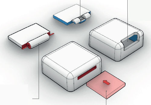
Shutoffs
Avoiding undercuts altogether may be the best option. Undercuts always add cost, complexity, and maintenance requirements to the mold. A clever redesign can often eliminate undercuts. Shut-offs are a useful trick to deal with undercuts on internal regions of the part (for snap-fits) or on the sides of the part (for holes or handles).
There are some examples of how injection molded parts can be redesigned to avoid undercuts: essentially, material is removed in the area under the undercut, eliminating the issue altogether.
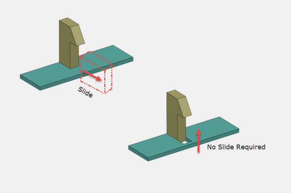
Sliding side actions
Sliding side-actions and cores are used when it is not possible to redesign the injection molded part to avoid undercuts. Side-action cores are inserts that slide in as the mold closes and slide out before it opens. Keep in mind that these mechanisms add cost and complexity to the mold.
Design Features
There are design rules for each design features to comply with the injection molding theory.
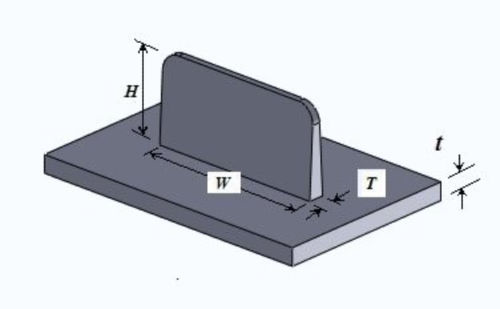
Ribs
Sometimes the maximum recommended wall thickness may not be enough to meet the functional requirements of a part, ribs can be used to improve its stiffness.
Recommended guidelines for ribs:
- Set it as a half the thickness of the wall thickness
- Limit the height smaller than 3 × rib thickness
- Use a base fillet with radius greater then quarter of the rib thickness
- Add a draft angle of at least 0.25 degrees
- Keep a distance between ribs and walls as 4 × rib thickness
Snap fit joints
Snap-fit joints are a very simple, low cost and quick way of joining two parts without fasteners. There are options exist for snap fit joints. The deflection of a snap-fit joint depends on its length and the force that is applied on it on its width. Snap-fit joints are another example of undercuts.
For more detailed information, please refer to this article from MIT. For better results, here are some guidelines:
- Add a draft angle to the vertical walls of your snap-fit joints
- Design snap-fits with thickness greater than 0.5x the wall thickness
- Adjust the width and length to control their deflection and permissible force
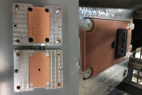
Text and Symbols
Text can be a very common feature that is useful for logos, labels, warnings, and instructions. That saves the cost for a label.
Embossed text is better than engraved text. It's easier to CNC machine on the mold and more economical. When text 0.5 mm above the part surface, the letters are easier to read. It is recommended a bold, rounded font style, with a size of 20 points or larger. For example: Century Gothic Bold, Arial and Verdana.
- Use embossed text (0.5 mm height) instead of engraved texted
- Use a font with uniform thickness and a minimum font size of 20 points
- Align the text perpendicular to the parting line
- Use a height (or depth) greater than 0.5 mm