Designing the mold in CAD (Fusion 360)
 |
| -Click to Go Back |
USE FUSION 360 or SIMILAR CAD SOFTWARE
The first step is to design the part in CAD software. The Fusion 360 is a powerful and also affordable option to use.
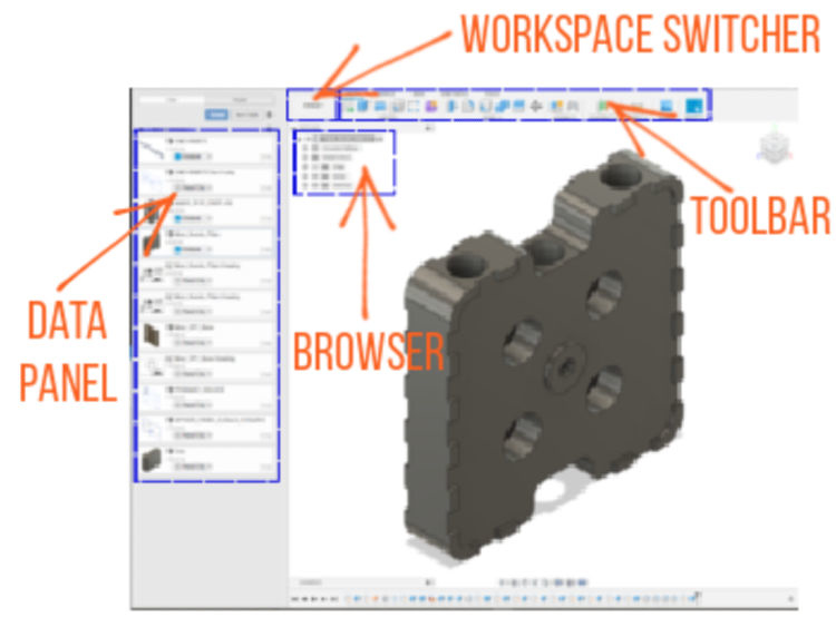
The layout for the Fusion 360 is a very clean layout to work with.
Once the part is designed in CAD, create a project for the mold you want to make. Add the template cavity and core files to your project.
Click on the cavity side in the data panel to start working on it.
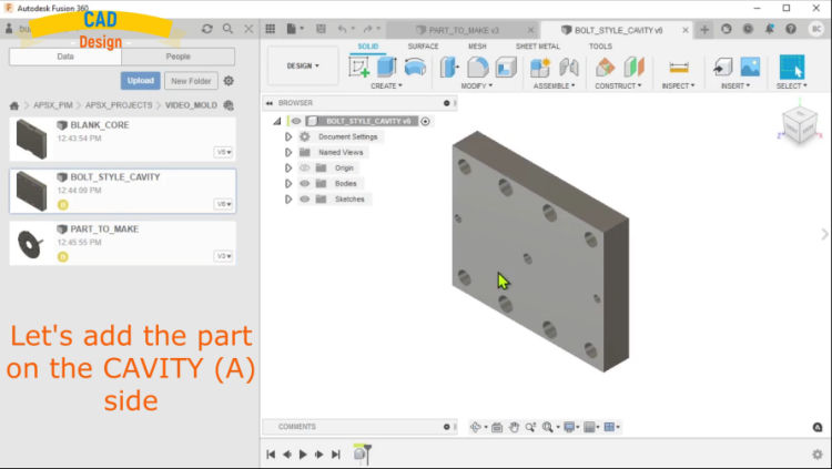
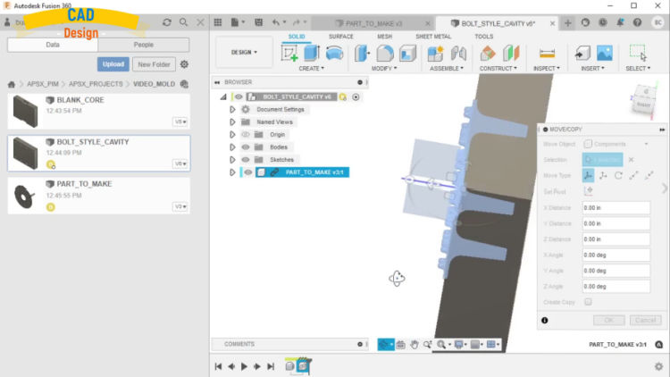
Add the part to the cavity mold by clicking on the part file on the left data panel. Then adjust the orientation based on your needs.
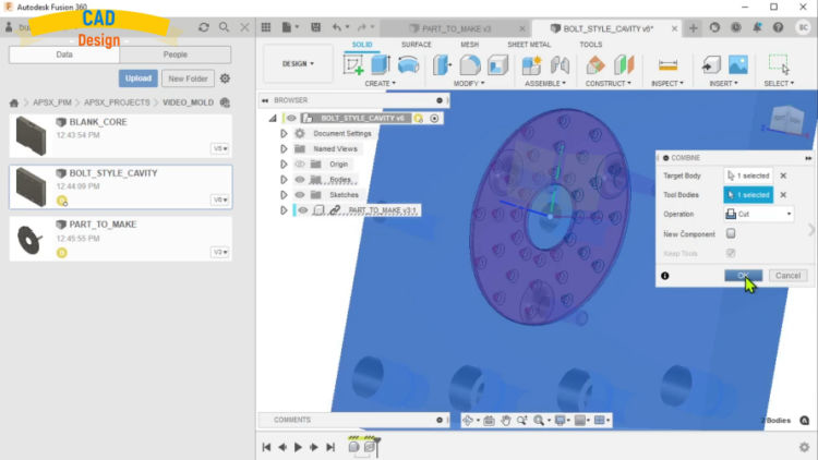
Click on Modify menu on the top section and select the combine option. Select the mold and cavity as two bodies. Select the cut option for the operation to cut out the part from the mold.
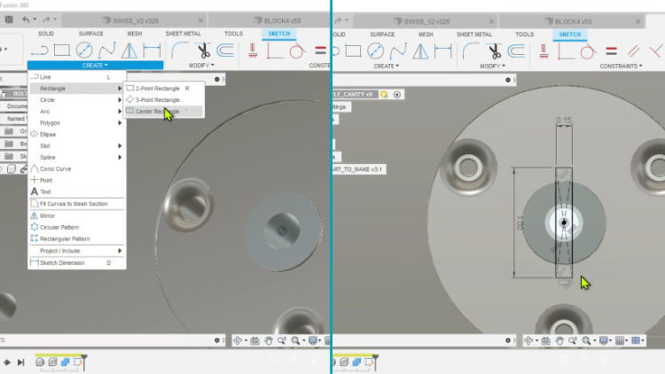
Runner/Gate design: Select the center plane and select CREATE/Rectangle from the menu. Click on the center, hold and drag a rectangle. Adjust the dimensions as 1" by 0.15".
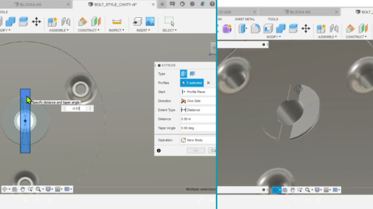
Select the rectangle and perform EXTRUDE (e) from the menu. Set the depth of extrusion as 0.03".
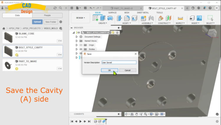
Select the SAVE icon on the top menu to save the final mold cavity file.
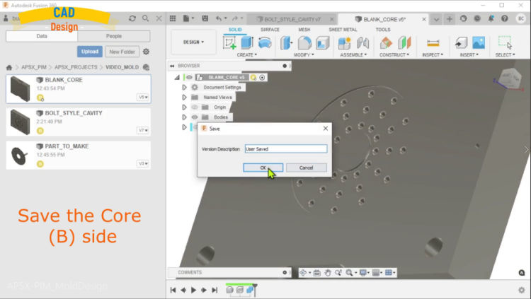
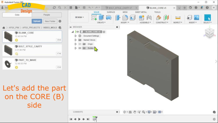
Now you can follow the same steps for the core (B) side. Click on the core side in the data panel to start working on it.
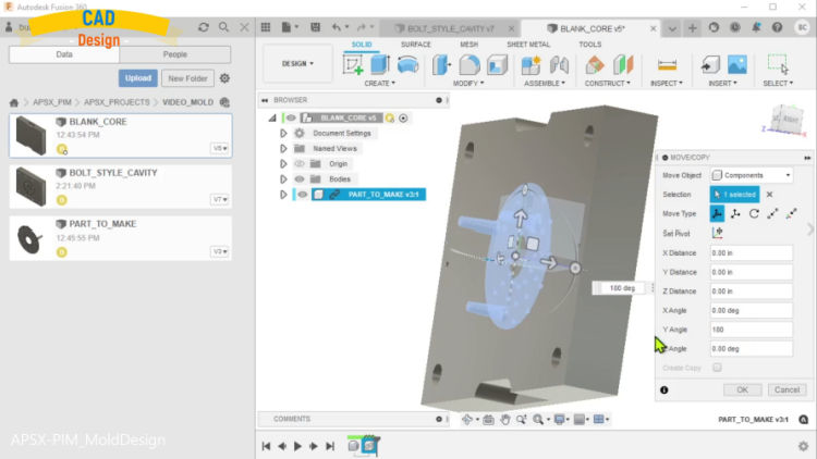
Add the part to the core mold by clicking on the part file on the left data panel. Then adjust the orientation based on your needs. You may need to flip the part 18- degrees.
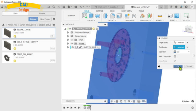
Click on Modify menu on the top section and select the combine option. Select the mold and core as two bodies. Select the cut option for the operation to cut out the part from the mold.
Inspect the final mold core and make adjustments if you need. Select the SAVE icon on the top menu to save the final mold core file.
You are ready to move on to the CAM part of creating the machining paths and the g-code file for CNC milling the mold.